10 Results
View results:
Sort by:

If you want to use a pure surface model, for example, when determining the internal forces and moments, but the structural component is still designed on the member model, you can take advantage of a result beam.

Very small torsional moments in the members to be designed often prevent certain design formats. In order to neglect them and still perform the designs, you can define a limit value in RF‑/STEEL EC3 from which torsional shear stresses are taken into account.

General thin-walled cross-sections often have asymmetrical geometries. The principal axes of such sections are then not parallel to the horizontally and vertically aligned axes Y and Z. When determining the cross-section properties, the angle α between the center-of-gravity axis y and the principal axis u is determined in addition to the principal axis-related moments of inertia.
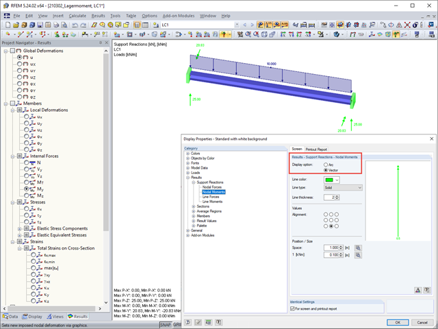
In the display properties, you can select Results → Support Reactions → Nodal Moments to specify whether a support moment should be displayed as an arc or a vector.
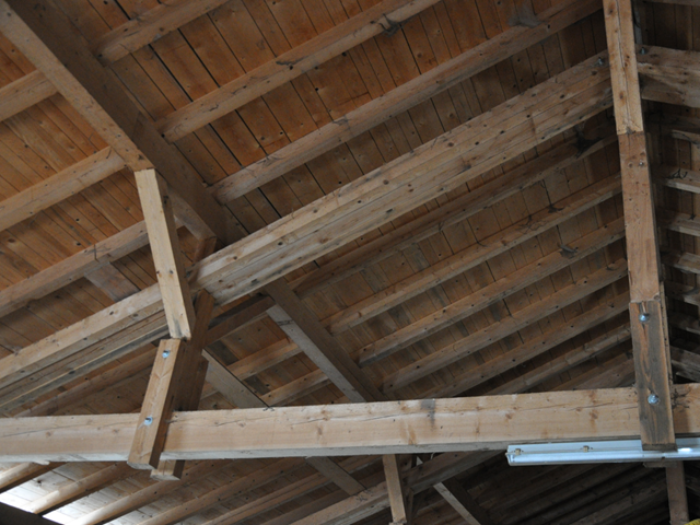
When modeling frame structures, RFEM and RSTAB provide various options for controlling the transfer of internal forces and moments at the connection points of members. You can use the member types to determine whether only forces act on the connected members, or whether moments act on them as well. In addition, you can use hinges to exclude specific internal forces from the transfer. One special form is scissor hinges, which allow for realistic modeling of roof structures, for example.
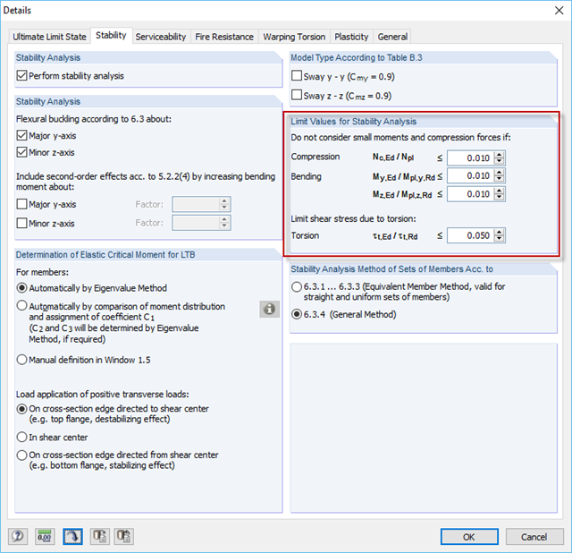
As of the program version X.11, the filter options of small compression forces or moments for stability analysis in RF‑/STEEL EC3 have been revised. The revision of these filter options in the "Stability" tab of the "Details" dialog box allows you to work in the module transparently, since they are now independent of the design.
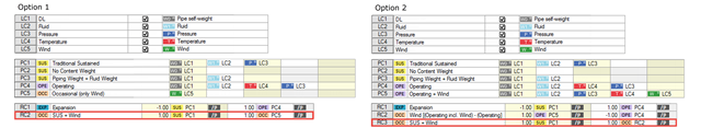
The RF-PIPING and RF-PIPING Design add-on modules allow you to design piping systems according to EN 13480-3 [1], ASME B31.1 and B31.3. In the case of the European standard, the determination of pipe stresses is based on the formulas of Section 12.3 Flexibility Analysis. Depending on the stress type, one or more resulting moments is applied without regard to each other. This differentiation occurs when determining the stresses due to occasional loads, for example.
![System and Loading According to [1]](/en/webimage/009634/2419765/01-en-png-png.png?mw=640&hash=5e657e3feb5c1bb6d21727468dd85d91e1c9f29f)
A structural analysis does not only determine and design internal forces and deformations. It also ensures that the forces and moments in a structure are generated in a reliable way and applied to the foundation. Dlubal Software provides a wide range of products for the structural analysis and design of steel and timber connections. The RF-/JOINTS Steel – Column Base add-on module allows you to design footings of hinged and restrained column bases. The design can be performed for column base plates with or without stiffeners.
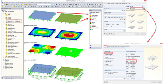
In a plate with full torsional stiffness, a significant part of the loads is transferred by torsional moments. If it is impossible to set the positive effect of this additional stiffness in the calculation (for example, due to a butt joint of a precast plate in the stiffness area), you have to reduce the torsional stiffness.
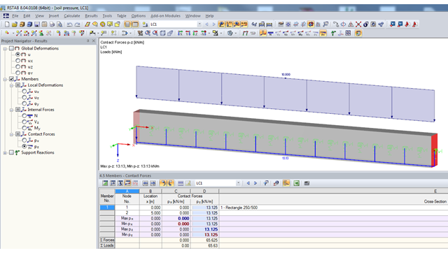
If a model should contain members with elastic foundations, the contact forces and moments are displayed in numerical form in the result windows. The graphical display of results is specified by the "Members" entry in the Results Navigator.